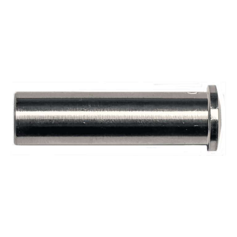
The Push-Lock® is a concealed, swageless, non-tensioning, through-the-post-mounted fitting that is suitable for use on level runs only, and is available for 1/8” and 3/16” diameter 1×19 stainless steel cable.
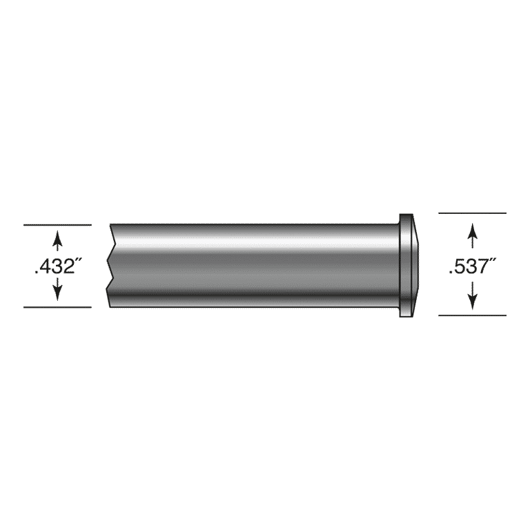
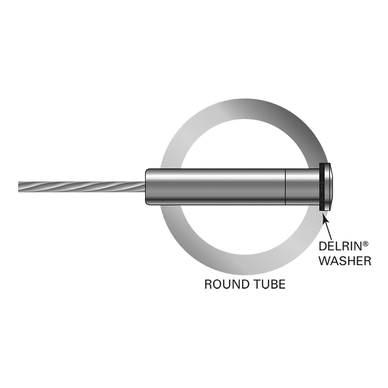
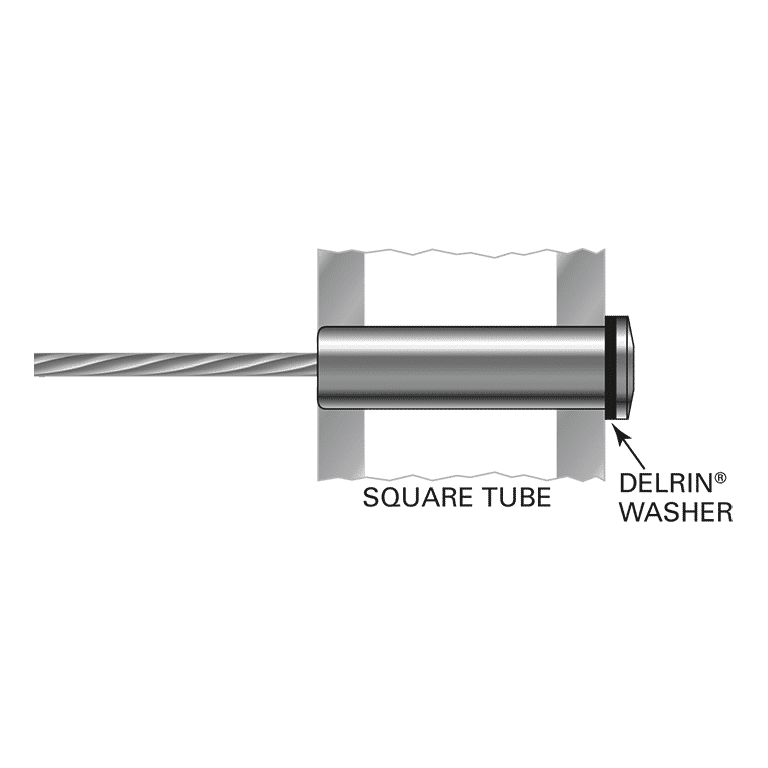
The Push-Lock® fitting must be used with a tensioning fitting on the opposite end of the run. This fitting is installed into a pre-drilled hole in the end post. Using the Push-Lock® fitting requires enough clearance on the back side of the end post (to install the fitting through the back side of the post) and that amount of clearance depends on the length of the Push-Lock® fitting chosen. This fitting is furnished with a Delrin® washer that is installed between the shoulder of the fitting and the end post to protect the surface of the finish of the end post as tension is applied. It is recommended that you choose a length of Push-Lock® that is the same as the cross section dimension of the end post. The cable attaches to the fitting via our Push-Lock® locking wedge system which requires no special tools.
This fitting is made to look similar to the Invisiware® Receiver from the exterior of the post, so it is recommended to use a Receiver with stud on the opposite end whenever practical to maintain a consistent look.
Specifications
Metal Framing Options for Push-Lock Fittings
Frame “F”
Frame “R”
Frame “P”
1/8″ Cable Part No.
3/16″ Cable Part No.
“L” Length
1-1/2″
1-1/2″
1-1/4″
PL-4-12
PL-6-12
1.562″
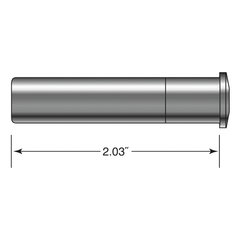
2″
2″
1-1/2″*
PL-4-2.030
PL-6-2.030
2.030″
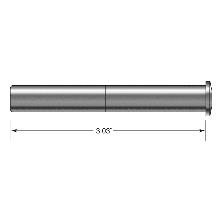
3″
3″
N/A
PL-4-3.030
PL-6-3.030
3.030″
*Will protrude from cable side of post +/- .125″
The Push-Lock® is a concealed, swageless, non-tensioning, through-the-post-mounted fitting that is suitable for use on level runs only, and is available for 1/8” and 3/16” diameter 1×19 stainless steel cable.
The Push-Lock® fitting must be used with a tensioning fitting on the opposite end of the run. This fitting is installed into a pre-drilled hole in the end post. Using the Push-Lock® fitting requires enough clearance on the back side of the end post (to install the fitting through the back side of the post) and that amount of clearance depends on the length of the Push-Lock® fitting chosen. This fitting is furnished with a Delrin® washer that is installed between the shoulder of the fitting and the end post to protect the surface of the finish of the end post as tension is applied. It is recommended that you choose a length of Push-Lock® that is the same as the cross section dimension of the end post. The cable attaches to the fitting via our Push-Lock® locking wedge system which requires no special tools.
This fitting is made to look similar to the Invisiware® Receiver from the exterior of the post, so it is recommended to use a Receiver with stud on the opposite end whenever practical to maintain a consistent look.