Choosing the Right Metal Cable Railing Framework
Ultra-tec® Metal Cable Railing Framework offers five (5) different cable diameters:
-
- 1/8″
- 3/16″
- 1/4″
- 5/16″
- 3/8″
For cable railings, you want to use a cable that is as rigid as possible and does not stretch. That is why we recommend 1×19 construction, type 316 stainless steel strand (cable). Other constructions such as 7×7 or 7×19 are less rigid than 1×19 and have elevated levels of stretch. The breaking strengths for 1×19 construction are also higher than 7×7 and 7×19.

Coated Cable
Any of our standard sizes of cable can be special ordered with a PVC coating to any standard color. However, using coated cable requires special hardware and hole specifications for frame components that differ from those shown in our design guides, boring diagrams, and other publications. PVC coatings have UV inhibitors, but they will deteriorate (fade, crack, peel) over time if exposed to sunlight. They also have a tendency to attract dust and dirt which may present a cleaning problem.
The 1×19 construction stainless steel strand (cable) is smooth to the touch and does not fray as easily as some other constructions, so there is no need to coat it for the purpose of creating a smooth, protective surface on the cable.
Cable Applications
| Cable Dia. | Typical Applications | ||
|---|---|---|---|
| 1/8″ | Now the most popular diameter for residential railing because it is the least expensive, most visually unobtrusive cable size. It is also the cable used for vertical railings. Since it is so thin, 1/8” diameter cable is also more susceptible to failure under shock loads than larger diameter cables. | ||
|
3/16″, 1/4″ |
3/16” and 1/4“ diameters are the most commonly used cable sizes for commercial railings. 3/16”, formerly the most popular size for residential railings, is still very popular with more safety-conscious homeowners. | ||
|
5/16″, 3/8″ |
5/16” and 3/8” diameter cables are truly the best choice when a visually robust appearance is desired. | ||
Cable Minimum Breaking Strengths
| Cable Dia. | Cable Type 316 Stainless Steel (Lbs.) | ||
|---|---|---|---|
| 1 x 19 | 7 x 7 | 7 x 19 | |
| 1/8″ | 1,780 | 1,360 | 1,300 |
| 3/16″ | 4,000 | 3,300 | 2,900 |
| 1/4″ | 6,900 | 5,500 | 4,900 |
| 5/16″ | 10,600 | 7,600 | 7,600 |
| 3/8″ | 14,800 | 11,700 | 11,000 |
Ultra-tec® hardware is designed for use in pedestrian guard railings. For other applications, consult the factory for suitability.
Cable Railing Parameters and Constraints
We will first address the issues encountered while designing a horizontally run cable railing system.
A horizontally run series of cables used as in-fill in a railing is legal in most jurisdictions. A few places, however, do not allow the “ladder effect” of horizontal in-fill elements. Therefore, the first step to be taken is to determine if the jurisdiction of the site will allow a “ladder effect” type of railing. If you are unable to use a horizontal railing, we offer a vertical cable railing system, which is described later on in this section.
Cable is very strong in tensile strength and is a suitable in-fill material for a railing. There are many different types of constructions of cable (also referred to as wire rope). Most cable is designed to be flexible for going over pulleys or for lifting/moving heavy loads. Other constructions of cable are designed to hold something in tension, such as guy wire or a sailboat stay, and are less flexible. For any particular diameter of cable, the tradeoff for flexibility is strength. The opposite is also true. You compromise strength when you require a construction of cable that is capable of a higher degree of flexibility.
Cable flexibility is an important consideration in designing a cable railing. The IRC and IBC require that a 4″ sphere shall not pass through any portion of railing/stair rail. Having the rigidity to prevent deflection of a horizontally run cable that is subjected to a vertical load is partly mitigated by the cable’s lack of flexibility. Therefore, it is our preference to use the most rigid of cable constructions possible when designing a railing using cable. The other factors are the tension of the cable, the span between supporting intermediate members, the diameter of the cable, and the vertical spacing of the cables on center.
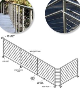
Let’s start with the spacing of your intermediate members, which are posts and/or braces, which will support the cable as it passes through the walls of the railing frame. (An intermediate post runs from the top rail to the mounting surface. A brace is a lighter weight material placed between posts, its primary purpose being to support the cable.) Cable can be run quite long distances between terminating ends (60 ft. or more, depending upon railing configuration), but it needs to be supported at intervals between end posts, to avoid cable deflection in excess of that permitted by building codes. When a rigid cable construction is used, such as 1×19, the spacing between posts and/or braces should not exceed 48″.
The next variable is the diameter of the cable. While 1/8″ is the cable diameter most often used for residential applications, we recommend it be used only in an area that is unlikely to experience heavy pedestrian traffic. For most applications, we suggest 3/16″ diameter cable. When the scale of the project is large, a larger diameter cable may be preferred from an aesthetics standpoint. We offer systems using up to 3/8″ diameter cable.
Spacing of the cables vertically is critical to minimize deflection of the cables under a vertical load. Our specifications provide recommended vertical spacing of 3-1/8″ on center for cables when they are installed.
The last variable is the tension of the cables and the construction of posts to which mounting and tensioning hardware is attached. Deflection of the end posts must be minimized, and this is where we have found the most mistakes made in the design of the railing framework. An incredible amount of force is placed on an end post when you have ten or more lines, each tensioned to a minimum of 225 lbs. over a height of 36″ to 42″. Often, designers and fabricators inexperienced in cable railings will not recognize the amount of the tension applied to the posts. The end result all too often is end posts which will bend considerably as the cables are being tensioned…or with a railing where the cables cannot be properly tensioned without an unacceptable amount of post deflection. The posts to which hardware is mounted must be constructed so that they will not deflect perceptively as the cables are tensioned to loads of 225 lbs. or more.
All of these variables work together to minimize the deflection of the cable so as to not allow a 4″ sphere to pass between the cables when they are properly tensioned in a well-designed frame.
Now, we will discuss issues encountered in designing a railing using vertically run cables as in-fill.
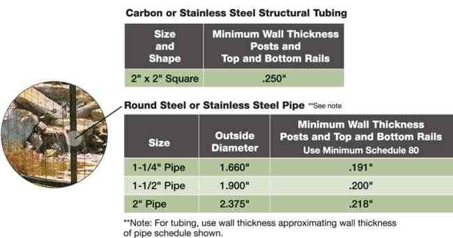
Top and bottom rails are necessary in a vertical railing using cable, because mounting and tensioning hardware is attached to top and bottom rails instead of end posts. We recommend schedule 80 pipe or 2″x2″x1/4″ square tubing for both the top and bottom rail, because of the forces applied when the cables are properly tensioned. However, the tension applied to a vertical cable is less than must be applied to a horizontally run cable. The result is less force being applied to the mounting and tensioning fittings. Therefore, you may consider using 1/8″ diameter cable with a vertical system, where you may not want to use it in a horizontal system.
Recommended Metal Frame Variations
Recommended frame components can be carbon steel or stainless steel. While aluminum posts are also very popular, because aluminum is weaker, the posts must have thicker walls for cable railing usage. We have not tested cable railing with aluminum posts or frames, so we are unable make any recommendations. The frames recommended below have been found to perform satisfactorily when subjected to the tension encountered when multiple load points (cables) are attached and tensioned properly to your end posts (225 lbs. per line). Detailed downloadable drawings show proper spacing of the cables vertically on the end posts that allow for cable flex within allowable limits to meet code requirements that a 4″ sphere shall not pass through at any point.
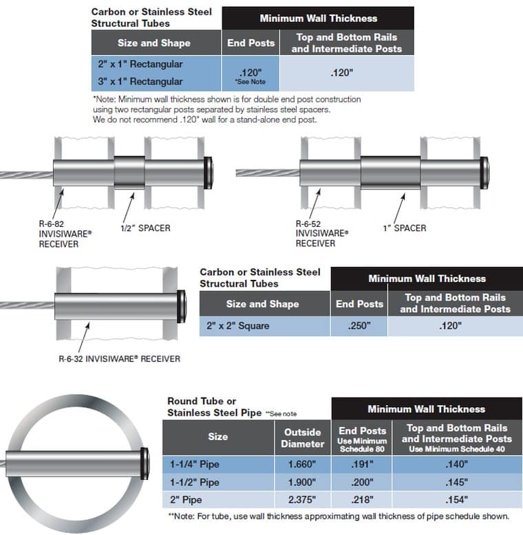
Using 2″x1″x.120″ or 3″x1″x.120″ Structural Steel Posts with Stainless Steel Spacers
Using 2″x1″ or 3″x1″ Top and Bottom Rail and Intermediate Posts (if applicable)
This railing style uses an end post with two vertical members separated by stainless steel spacers. Intermediate posts are only 1″ thick. This construction is strong yet its elements are relatively thin, so there is little visual obstruction created by the frame.
Using 2″x1″ Top Rail and Bottom Rail (if applicable)
Even though the end posts are 2″x2″x.250″, intermediate posts can be 2″x1″x.120″ to minimize the bulkiness of the frame.
Using 1-1/4″, 1-1/2″, or 2″ Standard Pipe
Detailed downloadable drawings for 1-1/4″, 1-1/2″ and 2″ standard pipe are available. Minimum schedule 80 pipe is required for your end posts.
Round tube can be used with a wall thickness at least comparable to schedule 80 pipe.
If you are using round tube, the downloadable drawings must be modified to allow for the different diameters of tube versus pipe.
Other Metal Frame Materials
Frame components other than those shown in this guide can be made using carbon steel or stainless steel. Other frame styles should be engineered to perform satisfactorily when subjected to the tension encountered when multiple load points (cables) are attached and tensioned properly to your end posts (225 lbs. per line).
Center-to-center spacings of the cables vertically on the end posts should be 3-1/8″, to allow for cable flex within allowable limits to meet code requirements that a 4″ sphere shall not pass through at any point.
METAL CABLE RAILING FRAMEWORK COMPONENTS MATERIAL SPECIFICATIONS FOR RAILINGS WITH HORIZONTALLY RUN CABLES
NOTE: We strongly recommend stainless steel for exterior applications.
DOWNLOADABLE DXF DRAWINGS - HORIZONTAL CABLE RAILING
Cable Railing Post Mounting Options
-
Core Mount End or Intermediate Post - Round
Drawing -
Core Mount End or Intermediate Post - Double Flat-Sided
Drawing -
Core Mount - Intermediate Post
Drawing -
Fascia Mount - End Post
Drawing -
Core Mount End or Intermediate Post - Square
Drawing -
Floor plate
Drawing -
Fascia Mount - Wood or Composite Deck
Drawing
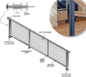
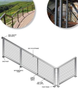
VERTICAL RAILINGS
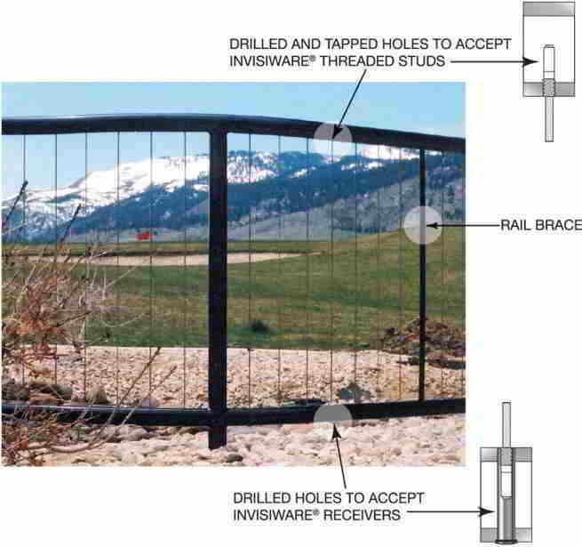
This railing frame style facilitates the use of cables in the vertical position, running from the top rail to the bottom rail.
The drawings on the following pages illustrate fabricating the railing from pipe. Square or rectangular tubing can also be used, but we recommend a minimum wall thickness of 1/4″ in your frame material.
An Invisiware® Threaded Stud on one end of the cable is screwed into a drilled and tapped hole in the underside of the top rail. An Invisiware® Receiver is inserted into a hole drilled through the bottom rail. A threaded stud on the other end of the cable is inserted into the receiver, and the cable is tensioned by turning the receiver with an Allen wrench.
Because the Invisiware® receiver goes all the way through a hole in the lower rail, a stainless steel frame must be used in exterior applications to prevent rust in the frame.
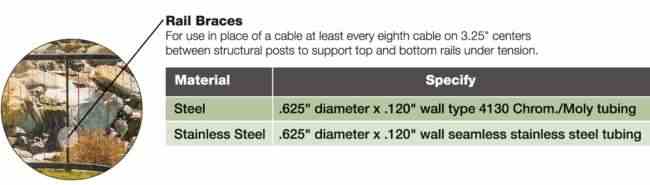
This frame has been shown to perform satisfactorily when subjected to the tension encountered when multiple load points (cables) are attached and tensioned properly on the top and bottom rails. Detailed downloadable drawings show proper spacing of the cables on the top and bottom posts to allow for cable flex within allowable limits to meet most code requirements (that a 4″ sphere shall not pass through at any point). Note that we recommend cable braces to replace every eighth cable to keep the top and bottom rails from bending when the cables are tensioned.
MATERIAL SPECIFICATIONS FOR RAILINGS WITH VERTICALLY RUN CABLES
For exterior applications, specify stainless steel to prevent rust in the railing frame.